Monday, 11 March 2024

My Feelings for death

 Kyu hoti hai kisi ki death, I don't know but why.

M aaj tak nhi samjh pae ki ensan ki death kyu hoti hai. Kisi se bhi pucho to ye jawab aata hai ki prakti ka niyam hai. Ye kesa niyam hai jisse kisi ka ghar ujad jata hai koi sadak par aa jata hai koi sadme se bhi nikal pta, koi depression ka sikar ho jata hai. But aakhir asa kyu. Kya aap log jante hai to please btaeyga jarur 

Friday, 6 January 2023

Parallel computing UNIT 1

INTRODUCTION

Paradigms of parallel computing:The evolution of parallel processing, even if slow, gave rise to a considerable variety of programming paradigms.

Independently from the specific paradigm considered, in order to execute a program which exploits parallelism, the programming language must supply the means to:

  1. identify parallelism, by recognizing the components of the program execution that will be (potentially) performed by different processors;
  2. start and stop parallel executions;
  3. coordinate the parallel executions (e.g., specify and implement interactions between concurrent components).

It is custom to separate the approaches to parallel processing into explicit versus implicit parallelism.

Parallel Programming:-Parallel computing refers to the process of executing several processors an application or computation simultaneously. Generally, it is a kind of computing architecture where the large problems break into independent, smaller, usually similar parts that can be processed in one go. It is done by multiple CPUs communicating via shared memory, which combines results upon completion. It helps in performing large computations as it divides the large problem between more than one processor.

Types of parallel computing

From the open-source and proprietary parallel computing vendors, there are generally three types of parallel computing available, which are discussed below:

  1. Bit-level parallelism: The form of parallel computing in which every task is dependent on processor word size. In terms of performing a task on large-sized data, it reduces the number of instructions the processor must execute. There is a need to split the operation into series of instructions. For example, there is an 8-bit processor, and you want to do an operation on 16-bit numbers. First, it must operate the 8 lower-order bits and then the 8 higher-order bits. Therefore, two instructions are needed to execute the operation. The operation can be performed with one instruction by a 16-bit processor.
  2. Instruction-level parallelism: In a single CPU clock cycle, the processor decides in instruction-level parallelism how many instructions are implemented at the same time. For each clock cycle phase, a processor in instruction-level parallelism can have the ability to address that is less than one instruction. The software approach in instruction-level parallelism functions on static parallelism, where the computer decides which instructions to execute simultaneously.
  3. Task Parallelism: Task parallelism is the form of parallelism in which the tasks are decomposed into subtasks. Then, each subtask is allocated for execution. And, the execution of subtasks is performed concurrently by processors.

Applications of Parallel Computing

There are various applications of Parallel Computing, which are as follows:

  • One of the primary applications of parallel computing is database and data mining.
  • The real-time simulation of systems is another use of parallel computing.
  • the technologies, such as networked videos and multimedia.
  • science and engineering
  • collaborative work environments.
  • The concept of parallel computing is used in augmented reality, advanced graphics, and virtual reality.

Advantages of Parallel Computing

Parallel computing advantages are discussed below:

  • In parallel computing, more resources are used to complete the task, which decreases the time and cuts possible costs. Also, cheap components are used to construct parallel clusters.
  • Parallel computing, as opposed to serial computing, can solve larger problems in less time.
  • For simulating, modeling, and understanding complex, real-world phenomena, parallel computing is much more appropriate than serial computing.
  • When the local resources are finite, they can offer advantages over non-local resources.
  • There are multiple problems that are very large and may impractical or impossible to solve them on a single computer; the concept of parallel computing helps to remove these kinds of issues.
  • One of the best advantages of parallel computing is that it allows you to do several things at once by using multiple computing resources.
  • Furthermore, parallel computing is suited for hardware, as serial computing wastes the potential computing power.

Disadvantages of Parallel Computing

There are many limitations to parallel computing, which are as follows:

  • It addresses a parallel architecture that can be difficult to achieve.
  • In the case of clusters, better cooling technologies are needed in parallel computing.
  • It requires managed algorithms, which could be handled in the parallel mechanism.
  • Multi-core architectures use a lot of energy.
  • The parallel computing system needs low coupling and high cohesion, which is difficult to create.

  Synchronous:-Synchronous execution means the first task in a program must finish processing before moving on to executing the next task whereas asynchronous execution means a second task can begin executing in parallel, without waiting for an earlier task to finish.


Real-World Examples

For those looking for another way to understand their differences or find a creative way to explain them to a pal, here are two real-world analogies.

Synchronous: You want a burger and decide to go to McDonald's. After you order the burger at the counter, you are told to wait as your burger is prepared. In this synchronous situation, you are stuck at the counter until you are served your burger.

Asynchronous: You want a burger and decide to go to Five Guys. You go to the counter and order a burger. Five Guys gives you a buzzer that will notify you once your burger is ready. In this asynchronous situation, you have more freedom while you wait.

Disclaimer: just to make sure we're aligned, we're not judging the performances of McDonald's and Five Guys here, this is purely fictional.

One type of programming is not inherently better than the other. They are just different, each with their own unique advantages, and are used in different scenarios. Depending on what you're building, you can and probably will use both sync and async tasks.

Technical Examples

We have selected 4 common examples of when synchronous and asynchronous processing are used in applications.

Synchronous Processing

·        User Interfaces: User interface (UI) designs are typically synchronous. Since UIs are spaces where humans and computers interact, it is ideal for them to replicate the communication standards and practices humans are familiar with. Humans expect an immediate response when they interact with a computer!

·        HTTP APIs: HTTP APIs pass requests and responses in a synchronous fashion. Client programs sending HTTP requests usually expect a fast answer from the web server.

Asynchronous Processing

·        Batch-processing: is a data-processing method to handle large amounts of data asynchronously. With asynchronous batch-processing, large batches of data are processed at scheduled times to avoid blocking computing resources.

·        Long-running tasks: such as fulfilling an order placed on an e-commerce site are best handled asynchronously. There is no need to block resources while this task is executed.


Thursday, 10 March 2022

operating system full notes

What is an Operating System? 
Intermediate between Hardware and Software applications.
Hides hardware complexity (Read/write file storage, send/receive socket network) Handles resource management (CPU scheduling, Memory management) 
Provide isolation and protection (allocate different parts of memory to different applications so that applications don't overwrite other memory locations)

 Operating System definition: 
An Operating System is a layer of systems software that: 
directly has privileged access to the underlying hardware; 
hides the hardware complexity;
manages hardware on behalf of one or more application according to some predefined policies. In addition, it ensures that applications are isolated and protected from one another. 

Operating System examples: 

 OS Elements 
Abstractions (corresponds to applications that OS executes) 
process, thread, file, socket, memory page 
Mechanisms (on top of Abstractions)
 create, schedule, open, write, allocate 
Policies (how mechanisms are used to manage underlying hardware) 
Least Recently Used (LRU) , Earliest Deadline First (EDF), etc. 

Example : Memory Management: Abstractions: Memory page Mechanisms: Allocate, map to a process Policies: LRU OS Design Principles Seperation of mechanism and policy implement flexible mechanisms to support many policies e.g. LRU, LFU, random Optimize for common case Where will the OS be used? What will the user want to execute on that machine? What are the workload requirements? User/ Kernel Protection Boundary user-level => applications [underprivileged mode] kernel-level => OS Kernel [privileged access, hardware access] userkernelprotectionboundary User-Kernel switch is supported by hardware. using trap instructions system calls like: open (file) send (socket) malloc (memory) signals System call Flowchart systemcallflowchart To make a system call, an application must: write arguments save relevant data ast well defined location make system calls using system call number In synchronous mode : wait until system call completes. Basic OS services process management file management device management memory management storage management security Linux System Calls Task Commands Process Control fork (); exit(); 
wait(); 
File Manipulation open(); 
read(); 
write(); 
Device Manipulation ioctl(); 
read(); 
write(); 
Information Maintenance getpid(); 
alarm(); 
sleep(); 
Communication pipe(); 
shmget(); 
mmap(); 
Protection chmod(); 
umask(); 
chown(); 

Monday, 31 January 2022

gk question for railway

 1. भारतीय राष्ट्रीय कांग्रेस की स्थापना 

Ans-1885 ई. 

2. बंग-भंग आंदोलन(स्वदेशी आंदोलन) 

Ans-1905 ई. 

3. मुस्लिम लीग की स्थापना 

Ans-1906 ई. 

4.कांग्रेस का बंटवारा 

Ans-1907 ई. 

5. होमरूल आंदोलन 

Ans1916 ई. 

6. लखनऊ पैक्ट 

Ans-दिसंबर 1916 ई. 

7. मांटेग्यू घोषणा 

Ans-20 अगस्त 1917 ई. 

8. रौलेट एक्ट 

Ans-19 मार्च 1919 ई. 

9. जालियांवाला बाग हत्याकांड 

Ans-13 अप्रैल 1919 ई. 

10. खिलाफत आंदोलन 

Ans-1919 ई. 

11. हंटर कमिटी की रिपोर्ट प्रकाशित 

Ans-18 मई 1920 ई. 

12. कांग्रेस का नागपुर अधिवेशन 

Ans-दिसंबर 1920 ई. 

13. असहयोग आंदोलन की शुरुआत 

Ans-1 अगस्त 1920 ई. 

14. चौरी-चौरा कांड 

Ans-5 फरवरी 1922 ई. 

15. स्वराज्य पार्टी की स्थापना 

Ans-1 जनवरी 1923 ई. 

16. हिंदुस्तान रिपब्लिकन एसोसिएशन 

Ans-अक्टूबर 1924 ई. 

17. साइमन कमीशन की नियुक्ति 

Ans-8 नवंबर 1927 ई. 

18. साइमन कमीशन का भारत आगमन 

Ans-3 फरवरी 1928 ई. 

19. नेहरू रिपोर्ट 

Ans-अगस्त 1928 ई. 

20. बारदौली सत्याग्रह 

Ans-अक्टूबर 1928 ई. 

21. लाहौर पड्यंत्र केस 

Ans-8 अप्रैल 1929 ई. 

22. कांग्रेस का लाहौर अधिवेशन 

Ansदिसंबर 1929 ई. 

23. स्वाधीनता दिवस की घोषणा 

Ans-2 जनवरी 1930 ई. 

24. नमक सत्याग्रह 

Ans-12 मार्च 1930 ई. से 5 अप्रैल 1930 ई. तक 

25. सविनय अवज्ञा आंदोलन 

Ans-6 अप्रैल 1930 ई. 

26. प्रथम गोलमेज आंदोलन 

Ans-12 नवंबर 1930 ई. 

27. गांधी-इरविन समझौता 

Ans-8 मार्च 1931 ई. 

28.द्वितीय गोलमेज सम्मेलन 

Ans-7 सितंबर 1931 ई. 

29. कम्युनल अवार्ड (साम्प्रदायिक पंचाट) 

Ans-16 अगस्त 1932 ई. 

30.पूना पैक्ट 

Ans-सितंबर 1932 ई. 

31. तृतीय गोलमेज सम्मेलन 

Ans-17 नवंबर 1932 ई. 

32. कांग्रेस सोशलिस्ट पार्टी का गठन 

Ans-मई 1934 ई. 

33. फॉरवर्ड ब्लाक का गठन 

Ans-1 मई 1939 ई. 

34. मुक्ति दिवस 

Ans-22 दिसंबर 1939 ई. 

35. पाकिस्तान की मांग 

Ans-24 मार्च 1940 ई. 

36. अगस्त प्रस्ताव 

Ans-8 अगस्त 1940 ई. 

37. क्रिप्स मिशन का प्रस्ताव 

Ans-मार्च 1942 ई. 

38. भारत छोड़ो प्रस्ताव 

Ans-8 अगस्त 1942 ई. 

39. शिमला सम्मेलन 

Ans-25 जून 1945 ई. 

40. नौसेना का विद्रोह 

Ans-19 फरवरी 1946 ई. 

41. प्रधानमंत्री एटली की घोषणा 

Ans-15 मार्च 1946 ई. 

42. कैबिनेट मिशन का आगमन 

Ans-24 मार्च 1946 ई. 

43. प्रत्यक्ष कार्यवाही दिवस 

Ans-16 अगस्त 1946 ई. 

44. अंतरिम सरकार की स्थापना 

Ans-2 सितंबर 1946 ई. 

45. माउंटबेटन योजना 

Ans-3 जून 1947 ई. 

46. स्वतंत्रता मिली 

Ans-15 अगस्त 1947 ई. 

प्रश्न:- स्वतंत्र भारत के प्रथम गवर्नर जनरल कौन थे? 

उत्तर:- लार्ड माउंटबेटन। 

प्रश्न:- भारत के प्रथम वायसराय कौन थे? 

उत्तर:- लॉर्ड कैनिंग। 

प्रश्न:- भारत की प्रथम महिला राजदूत कौन थी? 

उत्तर:- विजयलक्ष्मी पंडित। 

प्रश्न:- भारत के प्रथम परमाणु रिएक्टर का क्या नाम है? 

उत्तर:- अप्सरा। 

प्रश्न:- भारत की प्रथम महिला पायलट कौन थी? 

उत्तर:- प्रेमा माथुर। 

प्रश्न:- भारतीय वायुसेना की प्रथम महिला पायलट? 

उत्तर:- हरिता कौर देओल। 

प्रश्न:- भारतीय वायुसेना का प्रथम अधिकारी जिसने परमवीर चक्र प्राप्त किया? 

उत्तर:- निर्मलजीत सेंखो। 

प्रश्न:- भारत की प्रथम महिला लोकसभा अध्यक्ष? 

उत्तर:- मीरा कुमार। 

प्रश्न:- भारत के प्रथम साम्यवादी लोकसभा अध्यक्ष कौन थे? 

उत्तर:- सोमनाथ चटर्जी। 

प्रश्न:- भारत के पहले मुख्य चुनाव आयुक्त कौन थे? 

उत्तर:- सुकुमार सेन। 

प्रश्न:- भारत के पहले गृह मंत्री कौन थे? 

उत्तर:- सरदार वल्लभ भाई पटेल। 

प्रश्न:- भारत के पहले रक्षा मंत्री कौन थे? 

उत्तर:- सरदार बलदेव सिंह। 

प्रश्न:- भारत के पहले वित्त मंत्री कौन थे? 

उत्तर:- आर.के. षंमुखम चेट्टी। 

प्रश्न:- भारत किए पहले केन्द्रीय शिक्षा मंत्री कौन थे? 

उत्तर:- मौलाना अबुल कलाम आजाद।

Friday, 17 December 2021

Aptitude trick

 Important Formulas of Number System

Formulas of Number Series
1. 1 + 2 + 3 + 4 + 5 + … + n = n(n + 1)/2
2. (12 + 22 + 32 + ….. + n2) = n ( n + 1 ) (2n + 1) / 6
3. (13 + 23 + 33 + ….. + n3) = (n(n + 1)/ 2)2
4. Sum of first n odd numbers = n2
5. Sum of first n even numbers = n (n + 1)

Mathematical Formulas

1. (a + b)(a – b) = (a2 – b2)
2. (a + b)2 = (a2 + b2 + 2ab)
3. (a – b)2 = (a2 + b2 – 2ab)
4. (a + b + c)2 = a2 + b2 + c2 + 2(ab + bc + ca)
5. (a3 + b3) = (a + b)(a2 – ab + b2)
6. (a3 – b3) = (a – b)(a2 + ab + b2)
7. (a3 + b3 + c3 – 3abc) = (a + b + c)(a2 + b2 + c2 – ab – bc – ac)
8. When a + b + c = 0, then a3+ b3 + c3 = 3abc
9. (a + b)n = an + (nC1)an-1b + (nC2)an-2b2 + … + (nCn-1)abn-1 + bn

Shortcuts for number divisibility check

1. A number is divisible by 2, if its unit’s digit is any of 0, 2, 4, 6, 8.
2. A number is divisible by 3, if the sum of its digits is divisible by 3.
3. A number is divisible by 4, if the number formed by the last two digits is divisible by 4.
4. A number is divisible by 5, if its unit’s digit is either 0 or 5.
5. A number is divisible by 6, if it is divisible by both 2 and 3.
6. A number is divisible by 8, if the number formed by the last three digits of the given number is divisible by 8.
7. A number is divisible by 9, if the sum of its digits is divisible by 9.
8. A number is divisible by 10, if it ends with 0.
9. A number is divisible by 11, if the difference of the sum of its digits at odd places and the sum of its digits at even places, is either 0 or a number divisible by 11.
10. A number is divisible by 12, if it is divisible by both 4 and 3.
11. A number is divisible by 14, if it is divisible by 2 as well as 7.
12. Two numbers are said to be co-primes if their H.C.F. is 1. To find if a number, say y is divisible by x, find m and n such that m * n = x and m and n are co-prime numbers. If y is divisible by both m and n then it is divisible by x.

Shortcuts for ‘recurring decimal to fraction’ conversion

1. For recurring decimals of format ‘0.abababab…’ (ab repeats), equivalent fraction will be “repeating group (here ab)”/”as many 9’s as the number of digits in repeating group”
2. For recurring decimals of format ‘0.abbbbb…’ (b repeats), equivalent fraction will be (entire decimal group – non-repeating decimal group)/(as many 9’s as the number of repeating digits in the decimal part with as many 0’s as the number of non-repeating digits in the decimal part)
Frequently Asked Questions on Number System
• Given a number x, you will be asked to find the largest n digit number divisible by x.
• You will be given with a set of numbers (n1, n2, n3…) and asked to find how many of those numbers are divisible by a specified number x.
• Given a number series, find the sum of n terms, find nth term etc.
• Find product of two numbers when their sum/difference and sum of their squares is given.
• Find the number when divisibility of its digits with certain numbers is given.
• Find the smallest n digit number divisible by x.
• Which of the given numbers are prime numbers.
• Number x when divided by y gives remainder r, what will be the remainder when x2 is divided by y.
• Given relationship between the digits of number, find the number.

. BASIC FORMULAE:
1. Distance =Average speed × time taken
2. Average speed = Distance travelled/time taken
3. Time taken = Distance travelled/Average Speed
4. X km/hour = x*5/18 meter per second
5. Y meter/second = y×18/5 kilometer per hour.


• Find result of operations (additions, subtractions, multiplications, divisions etc) on given integers. These integers can be large and the question may look difficult and time consuming. But mostly the question will map onto one of the known algebraic equa

Wednesday, 8 December 2021

Database Management System

 MODULE 1

DBMS Architecture 

The architecture of DBMS depends on the computer system on which it runs. For example, in a client-server DBMS architecture, the database systems at server machine can run several requests made by client machine. We will understand this communication with the help of diagrams.

Types of DBMS Architecture

There are three types of DBMS architecture:

1. Single tier architecture

2. Two tier architecture

3. Three tier architecture

1. Single tier architecture

In this type of architecture, the database is readily available on the client machine, any request made by client doesn’t require a network connection to perform the action on the database.

For example, lets say you want to fetch the records of employee from the database and the database is available on your computer system, so the request to fetch employee details will be done by your computer and the records will be fetched from the database by your computer as well. This type of system is generally referred as local database system.

2. Two tier architecture

DBMS Architecture - 2-tier

In two-tier architecture, the Database system is present at the server machine and the DBMS application is present at the client machine, these two machines are connected with each other through a reliable network as shown in the above diagram.

Whenever client machine makes a request to access the database present at server using a query language like sql, the server perform the request on the database and returns the result back to the client. The application connection interface such as JDBC, ODBC are used for the interaction between server and client.

3. Three tier architecture

DBMS Architecture - 3 tier

In three-tier architecture, another layer is present between the client machine and server machine. In this architecture, the client application doesn’t communicate directly with the database systems present at the server machine, rather the client application communicates with server application and the server application internally communicates with the database system present at the server.

DBMS Three Level Architecture Diagram
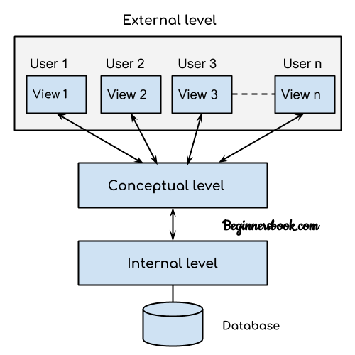
DBMS - Three Level Architecture

This architecture has three levels:
1. External level
2. Conceptual level
3. Internal level

1. External level

It is also called view level. The reason this level is called “view” is because several users can view their desired data from this level which is internally fetched from database with the help of conceptual and internal level mapping.

The user doesn’t need to know the database schema details such as data structure, table definition etc. user is only concerned about data which is what returned back to the view level after it has been fetched from database (present at the internal level).

External level is the “top level” of the Three Level DBMS Architecture.

2. Conceptual level

It is also called logical level. The whole design of the database such as relationship among data, schema of data etc. are described in this level.

Database constraints and security are also implemented in this level of architecture. This level is maintained by DBA (database administrator).

3. Internal level

This level is also known as physical level. This level describes how the data is actually stored in the storage devices. This level is also responsible for allocating space to the data. This is the lowest level of the architecture.

Data Abstraction 

Database systems are made-up of complex data structures. To ease the user interaction with database, the developers hide internal irrelevant details from users. This process of hiding irrelevant details from user is called data abstraction.
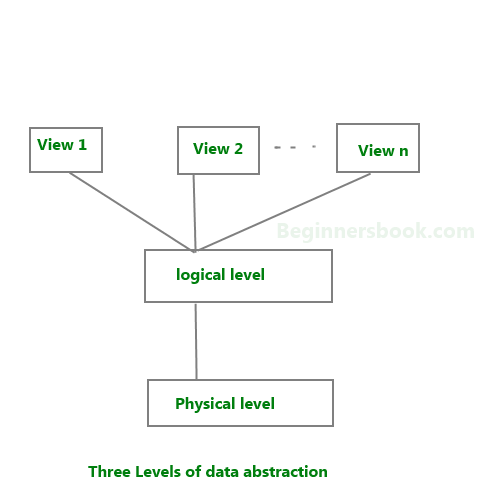
3 levels of abstraction

We have three levels of abstraction:
Physical level: This is the lowest level of data abstraction. It describes how data is actually stored in database. You can get the complex data structure details at this level.

Logical level: This is the middle level of 3-level data abstraction architecture. It describes what data is stored in database.

View level: Highest level of data abstraction. This level describes the user interaction with database system.

Example: Let’s say we are storing customer information in a customer table. At physical level these records can be described as blocks of storage (bytes, gigabytes, terabytes etc.) in memory. These details are often hidden from the programmers.

At the logical level these records can be described as fields and attributes along with their data types, their relationship among each other can be logically implemented. The programmers generally work at this level because they are aware of such things about database systems.

At view level, user just interact with system with the help of GUI and enter the details at the screen, they are not aware of how the data is stored and what data is stored; such details are hidden from them.

DBMS Schema

Definition of schema: Design of a database is called the schema. Schema is of three types: Physical schema, logical schema and view schema.

For example: In the following diagram, we have a schema that shows the relationship between three tables: Course, Student and Section. The diagram only shows the design of the database, it doesn’t show the data present in those tables. Schema is only a structural view(design) of a database as shown in the diagram below.
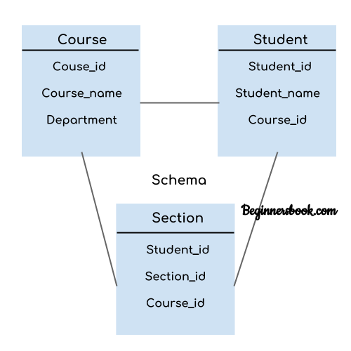
DBMS Schema

The design of a database at physical level is called physical schema, how the data stored in blocks of storage is described at this level.

Design of database at logical level is called logical schema, programmers and database administrators work at this level, at this level data can be described as certain types of data records gets stored in data structures, however the internal details such as implementation of data structure is hidden at this level (available at physical level).

Design of database at view level is called view schema. This generally describes end user interaction with database systems.

To learn more about these schemas, refer 3 level data abstraction architecture.

DBMS Instance

Definition of instance: The data stored in database at a particular moment of time is called instance of database. Database schema defines the variable declarations in tables that belong to a particular database; the value of these variables at a moment of time is called the instance of that database.

For example, lets say we have a single table student in the database, today the table has 100 records, so today the instance of the database has 100 records. Lets say we are going to add another 100 records in this table by tomorrow so the instance of database tomorrow will have 200 records in table. In short, at a particular moment the data stored in database is called the instance, that changes over time when we add or delete data from the database.

DBMS languages

Database languages are used to read, update and store data in a database. There are several such languages that can be used for this purpose; one of them is SQL (Structured Query Language).

Types of DBMS languages:
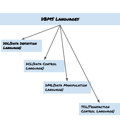
DBMS language

Data Definition Language (DDL)

DDL is used for specifying the database schema. It is used for creating tables, schema, indexes, constraints etc. in database. Lets see the operations that we can perform on database using DDL:

  • To create the database instance – CREATE
  • To alter the structure of database – ALTER
  • To drop database instances – DROP
  • To delete tables in a database instance – TRUNCATE
  • To rename database instances – RENAME
  • To drop objects from database such as tables – DROP
  • To Comment – Comment

All of these commands either defines or update the database schema that’s why they come under Data Definition language.

Data Manipulation Language (DML)

DML is used for accessing and manipulating data in a database. The following operations on database comes under DML:

  • To read records from table(s) – SELECT
  • To insert record(s) into the table(s) – INSERT
  • Update the data in table(s) – UPDATE
  • Delete all the records from the table – DELETE

Data Control language (DCL)

DCL is used for granting and revoking user access on a database –

  • To grant access to user – GRANT
  • To revoke access from user – REVOKE

In practical data definition language, data manipulation language and data control languages are not separate language, rather they are the parts of a single database language such as SQL.

Transaction Control Language(TCL)

The changes in the database that we made using DML commands are either performed or rollbacked using TCL.

  • To persist the changes made by DML commands in database – COMMIT
  • To rollback the changes made to the database – ROLLBACK

Data models in DBMS

Data Model is a logical structure of Database. It describes the design of database to reflect entities, attributes, relationship among data, constrains etc.

Types of Data Models

There are several types of data models in DBMS. We will cover them in detail in separate articles(Links to those separate tutorials are already provided below). In this guide, we will just see a basic overview of types of models.

Object based logical Models – Describe data at the conceptual and view levels.

  1. E-R Model
  2. Object oriented Model

Record based logical Models – Like Object based model, they also describe data at the conceptual and view levels. These models specify logical structure of database with records, fields and attributes.

  1. Relational Model
  2. Hierarchical Model
  3. Network Model – Network Model is same as hierarchical model except that it has graph-like structure rather than a tree-based structure. Unlike hierarchical model, this model allows each record to have more than one parent record.

Physical Data Models – These models describe data at the lowest level of abstraction.

Entity Relationship Diagram – ER Diagram 

An Entity–relationship model (ER model) describes the structure of a database with the help of a diagram, which is known as Entity Relationship Diagram (ER Diagram). An ER model is a design or blueprint of a database that can later be implemented as a database. The main components of E-R model are: entity set and relationship set.

What is an Entity Relationship Diagram (ER Diagram)?

An ER diagram shows the relationship among entity sets. An entity set is a group of similar entities and these entities can have attributes. In terms of DBMS, an entity is a table or attribute of a table in database, so by showing relationship among tables and their attributes, ER diagram shows the complete logical structure of a database. Lets have a look at a simple ER diagram to understand this concept.

A simple ER Diagram:

E-R Diagram

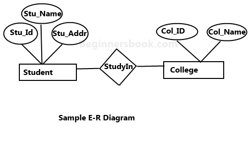
In the following diagram we have two entities Student and College and their relationship. The relationship between Student and College is many to one as a college can have many students however a student cannot study in multiple colleges at the same time. Student entity has attributes such as Stu_Id, Stu_Name & Stu_Addr and College entity has attributes such as Col_ID & Col_Name.

Here are the geometric shapes and their meaning in an E-R Diagram. We will discuss these terms in detail in the next section(Components of a ER Diagram) of this guide so don’t worry too much about these terms now, just go through them once.

Rectangle: Represents Entity sets.
Ellipses: Attributes
Diamonds: Relationship Set
Lines: They link attributes to Entity Sets and Entity sets to Relationship Set
Double Ellipses: Multivalued Attributes
Dashed Ellipses: Derived Attributes
Double Rectangles: Weak Entity Sets
Double Lines: Total participation of an entity in a relationship set

Components of a ER Diagram

ER Diagram Components


As shown in the above diagram, an ER diagram has three main components:
1. Entity
2. Attribute
3. Relationship

1. Entity

An entity is an object or component of data. An entity is represented as rectangle in an ER diagram.
For example: In the following ER diagram we have two entities Student and College and these two entities have many to one relationship as many students study in a single college. We will read more about relationships later, for now focus on entities.

ER diagram entity example
ER diagram weak entity example

Weak Entity:
An entity that cannot be uniquely identified by its own attributes and relies on the relationship with other entity is called weak entity. The weak entity is represented by a double rectangle. For example – a bank account cannot be uniquely identified without knowing the bank to which the account belongs, so bank account is a weak entity.

2. Attribute

An attribute describes the property of an entity. An attribute is represented as Oval in an ER diagram. There are four types of attributes:

1. Key attribute
2. Composite attribute
3. Multivalued attribute
4. Derived attribute

1. Key attribute:

ER diagram key attribute

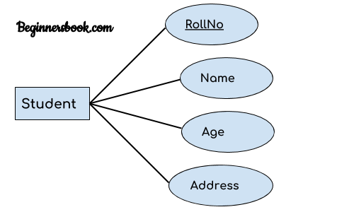
A key attribute can uniquely identify an entity from an entity set. For example, student roll number can uniquely identify a student from a set of students. Key attribute is represented by oval same as other attributes however the text of key attribute is underlined.

2. Composite attribute:

ER diagram composite attribute

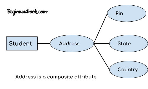
An attribute that is a combination of other attributes is known as composite attribute. For example, In student entity, the student address is a composite attribute as an address is composed of other attributes such as pin code, state, country.

3. Multivalued attribute:

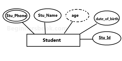
An attribute that can hold multiple values is known as multivalued attribute. It is represented with double ovals in an ER Diagram. For example – A person can have more than one phone numbers so the phone number attribute is multivalued.

4. Derived attribute:

A derived attribute is one whose value is dynamic and derived from another attribute. It is represented by dashed oval in an ER Diagram. For example – Person age is a derived attribute as it changes over time and can be derived from another attribute (Date of birth).

Multivalued and derived attribute

E-R diagram with multivalued and derived attributes:

3. Relationship

A relationship is represented by diamond shape in ER diagram, it shows the relationship among entities. There are four types of relationships:
1. One to One
2. One to Many
3. Many to One
4. Many to Many

1. One to One Relationship

ER diagram one to one relationship example

When a single instance of an entity is associated with a single instance of another entity then it is called one to one relationship. For example, a person has only one passport and a passport is given to one person.

2. One to Many Relationship

ER diagram one to many relationship example

When a single instance of an entity is associated with more than one instances of another entity then it is called one to many relationship. For example – a customer can place many orders but a order cannot be placed by many customers.

3. Many to One Relationship

ER diagram many to one relationship example

When more than one instances of an entity is associated with a single instance of another entity then it is called many to one relationship. For example – many students can study in a single college but a student cannot study in many colleges at the same time.

4. Many to Many Relationship

ER diagram many to many relationship example

When more than one instances of an entity is associated with more than one instances of another entity then it is called many to many relationship. For example, a can be assigned to many projects and a project can be assigned to many students.

Total Participation of an Entity set

Total Participation Diagram

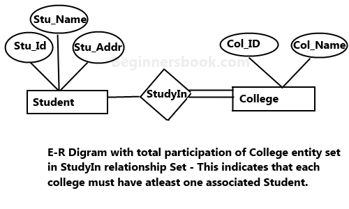
A Total participation of an entity set represents that each entity in entity set must have at least one relationship in a relationship set. For example: In the below diagram each college must have at-least one associated Student.


My Feelings for death

 Kyu hoti hai kisi ki death, I don't know but why. M aaj tak nhi samjh pae ki ensan ki death kyu hoti hai. Kisi se bhi pucho to ye jawab...